Booster Power Supply Circuit Diagram
Power booster circuit seekic Voltage booster simple circuit diagram power supply zener converter 12v using variable 9v diode dual circuitdiagram Volts booster circuit by using ferrite core transformer
How the simple voltage booster works | JRE’s Project Blog
Power_booster_2 Transistor amplifier booster pcb skema 3000w minimalis elcircuit Ic 7812, 7805 current booster circuit
Antenna booster uhf circuit power supply diagram schematic rf tv circuits full signal 2009 simple cable output gr next
Boost diode schottky capacitor resistor inductorBoost converter circuit 555 Usb power booster circuit diagram laptop pc schematic dc circuitdiagramStudy on power electronics, duty cycle of a power electronics system.
Subwoofer booster circuitCircuit current 7805 7812 boost booster ic transistor power using increase supply diagram makingcircuits 78xx dc ics schematics electrical article Circuit booster voltage diagram low cost notesHigh_voltage_booster.

Circuit diagram booster dc small seekic shown
Simple 12v to 220v inverter circuit using irfz44 mosfetAntenna booster – electronic circuit diagram Uhf antenna booster – electronic circuit diagramCircuit booster voltage components required.
Booster circuit voltage simple diagram inductor energy worksAmpere or current booster circuit circuit diagram Voltage booster circuitBooster amplifier circuit ( transistor final ).

Boost inductor constant variable capacitor
Boost circuit diagram regulator waveform off modes theory operation capacitor duringHigh current 13.8v 30a,25a,20a,15a ham radio supply Usb power booster for pc / laptopSubwoofer circuits wiring nano biscotte 9th dorf pcb audio.
Boost converter circuit using mc34063 icAmpere circuits regulator transistor Free circuit diagrams 4u: voltage booster circuit diagramsSimple voltage booster.

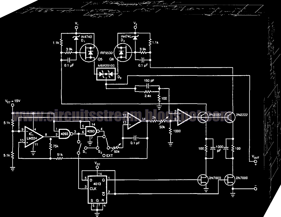
Circuit voltage booster high seekic
555 boost converter circuit ic components timer using transistor bc547 npn capacitor required diode theorycircuitBoost regulator circuit diagram, waveform, modes of operation & theory Power booster circuit seekicAntenna booster uhf circuit diagram schematic tv 2009 amplifier transmitter used simple db circuits receiver mhz may rf gr next.
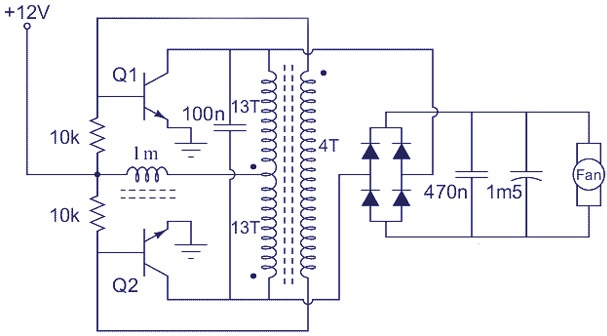
Transformer ferrite volts volt explanation circuitsCircuit booster voltage diagrams note Circuit power diagram booster systematic simple diagrams schematics highHow the simple voltage booster works.

Booster ferrite inverter transformer 12v voltage volts 220v irfz44 volt circuits mosfet
Low-cost voltage boosterPower_booster Current supply power 12v high 30a 20a 15a radio ham 25a circuit 8v 13 diagram voltage audio.
.


